Installing a manifold for a heated floor with your own hands. How to make a manifold for polypropylene pipes? Distribution manifold for heated floors made of polypropylene
A warm water floor is a good alternative or addition to radiator heating in a private home. The system can be installed either in one room or for the entire building. In both cases, it must be autonomous and ensure reliable operation of heating circuits with coolant. To solve this problem, you must install a manifold for a warm floor with your own hands, which is assembled from its constituent elements. The collector and heated floors are inextricably linked.
The main function of the device is the specified distribution of coolant throughout all circuits. It can be either uniform or selective.
A water floor system usually contains several circuits for distributing coolant through pipes. Each of them has a separate input and output connected to the collector. It consists of two combs: from one, hot water is supplied to, and in the other, its return flows, which have given up part of the heat, are combined together and returned for heating.
Preparing the coolant involves mixing hot and cold water to obtain the required temperature. Warm floors do not require a lot of heating of the coolant. If the temperature in radiators is 70-95°C, then for heated floors it does not exceed 30-55°C. It is impossible to walk barefoot on hot ceramic tiles, and other coatings warp due to high temperatures.
The manifold uses a mixing unit, which is a pump with pipelines that ensures mixing of the forward flow with the return flow and obtaining one with a certain temperature. The best method is sequential mixing (Fig. below), where the highest productivity is achieved.

Red arrows indicate the flow of hot coolant, blue arrows indicate coolant flow. The temperature of the mixture in front of the upper comb is controlled by a thermostatic valve.
The mixer is also used in systems where underfloor heating is combined with radiator heating. The ratio of portions of hot and cooled coolant is maintained by valves while temperature is controlled by heat, pressure and weather sensors. Natural circulation is no longer used in many places, and pumps are connected to the collectors to maintain pressure in the system.
In simple systems, the coolant is not mixed. It is supplied by a circulation pump installed in the return pipeline.
Collector cabinet
The mixing and distribution point for coolants will not look aesthetically pleasing if it is not hidden in a closet. Its price is low and it’s easier to buy it than to make it yourself if you don’t have the necessary tools. Cabinet designs are most often used built-in, but they can also be external.

They have holes for fastening. Fixation methods are always described in detail in the instructions. You should pay attention to this when purchasing. It is also important where the piping openings are located in the cabinet and how they fit into the manifold design. All its parts must be freely placed and have access for maintenance and repair. The cabinet must be securely closed so that only those servicing the system can access the equipment.
To assemble the collector yourself, you need the following elements:
- two- or three-way valve;
- shut-off and balancing valves. When the coolant temperature changes, the valve changes the flow area, regulating the liquid flow;
- pressure and temperature sensors;
- circulation pump;
- air vent (manual or automatic);
- elements for installation: fittings, tees, adapters, detachable couplings, etc.
The collector shown in Fig. below, makes it possible to connect several circuits, the number of which depends on the total area of the premises.

The pipes are connected with tapered fittings and are equipped with shut-off valves.
Creating a heating project
The project is a diagram of the location of branches and their connection to the collector. In this case, it is necessary to take into account a large number of factors on which the performance and ease of use of the system depends:
- number of circuits;
- type and characteristics of the heat source;
- description of additional energy sources that are expected to be installed later (boilers running on other fuels, solar panels, etc.);
- description of the operation of the main and additional equipment (sensors, measuring instruments, valves, expansion tanks, etc.);
- determination of the parameters of each device on the coolant injection and return lines;
- The pipe inlet from the boilers is located at the ends of the horizontal combs, and the heating circuits are located at the top and bottom.
Assembling the manifold from components
The collector is sold as a disassembled kit. It is not difficult to assemble if you first read the instructions. Most devices are assembled in the following sequence:
- The pipes are removed from the packaging and the sections are connected to each other.
- The combs are attached to the brackets.
- Install shut-off valves, control devices, connection elements and plugs.
- The assembled collector is mounted on the wall.
- The circulation pump and valve are connected.
- Pipes from the boiler and heating circuits are connected to the unit.
Important! The collector is assembled, connected to the pipes and configured before pouring the screed. The operation of control devices and adjustment of operating modes are checked. All circuits should work.
Materials
There are many models of collectors on the market and their choice largely depends on the heating scheme. They work with coolants at different heating levels. Therefore, high demands are placed on the material. Devices made of stainless steel and brass are very durable. In simple heating schemes, you can use plastic products, which are made at a high level by leading manufacturers.
How to assemble a collector with your own hands
It is impossible to directly connect a heated floor to the boiler with your own hands. For this you need a manifold with valves. It is installed in a cabinet, and the piping begins from there. The collector is provided with access to only one person who will service the system.
The range of collectors in stores is quite large, but it is often difficult to choose the right one for your heating system. In addition, a switchgear is needed on each floor of a private house, which leads to a significant increase in costs. A homemade manifold for heated floors is the right solution, allowing you to save a significant amount of money.
Connection
Since the heating system has a supply and return branch, the collector must consist of two combs connected to them. At the joints, branches are installed to drain water and remove air from the pipes.
The collector is assembled according to the number of connected loops. At each outlet, located at the top or bottom of the comb, taps are installed to ensure that individual circuits are turned off while the rest of the heating is running. It is recommended to make the distance between them 10-20 cm.
Manifold manufacturing
Before assembling a manifold for a heated floor, you need to understand the purpose of each element. It is recommended to make combs with your own hands from a square pipe. Round threaded pipes are welded to them for connection to the boiler and to the circuits. To do this, markings are first made, then holes are drilled, and then the pipes are attached. All joints are thoroughly scalded. A plug is made at one of the ends.
The scale is knocked off, the collector is cleaned and painted with oil compounds. In Fig. Below is a simple 3 loop manifold. The comb and coolant supply pipes from the boiler are painted red, and the return pipes, through which cooled water is supplied to heating, are blue.

Air vents are connected to the top of the combs, and plugs are installed at the bottom to discharge sludge. Each circuit can be closed with valves, which also serve to regulate temperature and pressure.
The distribution manifold is designed to control a small system that serves as additional heating. It will be much more complex if used for the main heating system in a large house. Assembling a manifold from polypropylene pipes is much simpler, but the simplest models are made this way.

Assembly of the collector unit
The underfloor heating manifold contains devices that ensure efficient operation of the system. Each circuit must have control valves. For a complex system, it is advisable to install automatic control valves.
Usually they operate in constant mode, the coolant flow changes only at the main supply inlet. For house areas up to 200 m², two-way valves are used. Their advantage is smooth adjustment. Valves often become clogged. Therefore, they are installed on detachable couplings (“American”) so that they can be removed for cleaning.
A more complex device is the three-way valve. It ensures mixing of forward and reverse water flows, maintaining the specified temperature at the outlet. Inside it there is a movable partition that regulates the flow of water from two inlet pipes. The device is used in all complex systems with automatic control of a large number of circuits. Its advantage is its significant throughput.
With the slightest turn of the tap, the temperature regime of the system changes. The adjustment can be manual or automatic. A three-way valve is often combined with a servo drive operating from an outdoor air temperature sensor. When the weather changes, the temperature in the rooms is maintained constant. As soon as cooling occurs, a signal from the weather sensor enters the control unit and the coolant temperature rises.
If the heated floor serves as the main heater of the house, the temperature of the coolant in the boiler can be maintained lower, which reduces the load on all equipment.
Video
The collector is the most important component of a heated floor system. With its help, the temperature in the rooms is regulated, economical energy consumption and long-term operation of the heating network are ensured. Therefore, choosing a device and installing it yourself should be taken with full responsibility.
Independent design and installation of heated floors is a responsible undertaking that requires a competent approach. It is very important for all those who have decided to independently install a manifold for a heated floor with their own hands to take into account absolutely every nuance and trifle that is insignificant at first glance, otherwise in the future the efficiency and performance of the entire heating system will be a big question.
In addition to the fact that the owners of the premises need to take care in advance about choosing the material of the pipes and drawing up a diagram of their location, it is very important to ensure that the coolant is evenly distributed throughout the entire system. It is for these purposes that a collector is installed, the main purpose of which is to preserve and maintain a given heat balance in the system.
So what is a collector?
Considering the fact that for the normal functioning of the entire water heated floor system, it is necessary to provide in advance for the presence of several entry points for the coolant, it is recommended to initially plan how exactly it will be distributed throughout the system.

As a rule, the collector assembly includes two combs, through one of them the liquid is supplied from the heating system to the pipes installed for the heated floor, and the other is designed to combine the return flows of the cooled coolant.
The most popular collector schemes
The underfloor heating manifold is one of the key components of the room heating system. In technical terms, it is a separate group of pipes assembled according to a certain pattern, allowing the combination of several water flows into one.
In practice, three pipe connection options are most often used:
- Parallel circuit of mixing branches;
- Sequential circuit;
- Combined connection type.
How to choose the most optimal one? When using a parallel circuit for connecting coolant branches, a portion of the thermal energy is often lost. Its use is due to the fact that it allows the installation of a two-way valve, adding a convenient control element to the circuit.
Sorry, nothing found.
The second option has the highest performance compared to all other schemes.
When using a sequential circuit in a home heating system, the consumer has the opportunity to obtain the maximum amount of thermal energy.
In turn, installing a combined connection diagram for a heated floor collector allows you not only to quickly install the entire system, but also to do it yourself, without resorting to the help of specialists.
What determines the choice of collector?
The choice of the most suitable model of equipment of this type depends on the heating floor installation scheme used and the location of the collector. It is important to remember that the design of the collector includes coolants characterized by different levels of heating, which makes this equipment an extremely vulnerable element of a water heated floor. For its efficient and completely safe operation, it is recommended to use components made of high-quality material with the highest strength characteristics.
 Modern collector material is stainless steel.
 Most often, the faucet itself is made of brass, however, recently you can find models made of stainless steel on the market. The final cost of the product will depend on its completeness. If desired, the owner of the premises can either choose very simple options or models equipped with various sensors, drain valves and thermal control units.
No less attention must be paid to the selection of all other components of the heating system - thermostatic equipment and pump, which must be of high quality and absolute reliability. If you plan to install several heating circuits, it is possible to install on each of them its own thermostat and flow sensors. Such a manifold for a heated floor is supplied complete with a thermal probe, a diverter device and a mixing tap; their installation is not difficult and, if necessary, can be done by hand.
 The circulation pump is an important element of the system.
 When servicing several circuits with one collector, the length of one loop should not exceed 115-118 centimeters. If a water heated floor is installed in a small room, it is permissible to use a collector made of plastic and having a simple temperature control system.
In recent years, various control elements have increasingly been added to the design of underfloor heating collectors, which allow them to be used not only as a distribution system, but also as a full-fledged control point for the entire heating system of a room. The simplest option would be to use a scheme that provides in the design of the collector, in addition to the common pipe, also control valves.
 Manifold control valve.
 Such solutions are perfect for heated floors with water circuits of different sizes. Having decided to install such a warm floor collector, it is necessary to provide in advance the possibility of mechanical adjustment of each shut-off valve, which allows you to obtain the most acceptable results at the output.
A more efficient design of the device will be a design that ensures the automatic operation of the collector, the operation of which will change depending on the current temperature of the coolant. You can see similar devices in the illustrative photos in the article. Such schemes can include a large number of different elements.
 Device diagram.
 The hot water inlet system is designed to distribute fluid evenly throughout the system. For all those who plan to independently install a manifold for a water-heated floor, experts recommend installing each inlet with its own control valve. Even an ordinary homeowner who is not used to doing anything with his own hands can cope with this task.
A return manifold into which cooled liquid will flow from the pipes of the floor heating system.
A balancing flow meter, which will act as the main control mechanism to ensure uniform flow of coolant throughout the water circuit.
 Temperature sensor.
 Exhaust valve designed for emergency air release. It is indispensable when the pressure in the pipes increases excessively. Temperature sensors that allow you to monitor the temperature of the water in the system. It is important to remember that the maximum water heating allowed in water-heated floor pipes is 55°C.
A circular pump will improve the efficiency of a water heated floor. The pump increases the speed of fluid passage in the system and is responsible for mixing warm and cold coolant.
Each of the elements described above is very important for the entire warm water floor system. That is why it is necessary to pay as much attention as possible to their selection and subsequent installation.
Benefits of using a collector
As practice shows, the use of a collector in a water heated floor system has a number of undeniable advantages, such as:
- Safety – the end consumer of thermal energy is completely protected from mechanical and thermal injuries;
- Hygienic and environmentally friendly - eliminates the possibility of bacteria, mold and fungi;
- Durability and the highest performance characteristics - with proper installation of the collector and compliance with all the basic rules for its selection and installation, the heating system will faithfully serve for at least 50 years;
- Economical - the ability to control the temperature in the system saves up to 50 percent of thermal energy consumption.
It should be noted that independent installation and connection of a water floor collector, in principle, should not raise questions even for a person with a minimum set of theoretical and practical construction skills. The main thing here is to strictly follow the recommendations and instructions of specialists and choose the right product components.
Installation work
When carrying out self-assembly and installing a heated floor collector with your own hands, it is very important to choose the right place; the appropriate video instructions will help you choose it.
For safety, it is recommended to place the entire collector structure in a special protective box, access to which must be completely free.
As a rule, the distribution point is placed in the wall space at approximately the same distance from the end lines, thereby ensuring the maintenance of the specified hydraulic mode during the operation of the system.
 An example of a house heating system with a heated floor collector.
 If it is not possible to fulfill these conditions for one technical reason or another, it is necessary to install two collectors, the heat load between which will be distributed evenly.
Cabinet Installation
Quite expectedly, it does not have sufficient aesthetics, which is why most owners of residential premises prefer to hide it in a special cabinet, which also performs protective functions. In principle, you can make such a cabinet with your own hands, or you can purchase a ready-made one, which will have all the necessary openings for the outlet and inlet pipelines. Installation of such cabinets does not take much time and requires a minimum of knowledge and skills. The edges of the supply and return pipes are inserted inside the protective box, and special shut-off valves are installed at the inlet openings.
 Manifold cabinet with lock.
 The cabinet is attached to the wall surface using small holes in the body. Depending on the type of construction, options for fixing the box to a vertical plane may differ in some specific features.
Installation and connection
To properly install manifolds for heated floors with your own hands, it is very important to have at least theoretical knowledge about the structure of the heating system at home. As mentioned above, the entire design of the system consists of two lines of pipes connected to each other. One line is designed to regulate the pressure of warm liquid, and the other is designed to remove already cooled water from the system.
After selecting and purchasing a collector, you need to install it in a cabinet prepared in advance. The final and most critical stage of the work will be connecting the collector to the general heating system. To do this, shut-off valves are installed on each pipe in the heated floor circuit, which allow, if necessary, to turn off the heating of the room from the general house system. It is important to know that absolutely all underfloor heating manifolds must be equipped with shut-off and control valves, which will allow you to completely turn off the water circuit or manually change the volume of coolant flow.
Not everyone has the opportunity to buy a ready-made collector, since the prices for them are often quite impressive. But it's not scary. From this article you will see that it is quite possible to assemble or even make DIY manifold for heated floors.
What do you need to assemble a manifold for a heated floor with your own hands?
The complete manifold may be prohibitively expensive. But not everything that can be in the assembly is necessary. Here is a list of what must be in the collector:
- the supply and return manifolds themselves;
- threads for ball valves (and, of course, the ball valves themselves);
- thermometers;
- tap with fitting - for filling the system;
- automatic air vents;
- threads for connecting Eurocones;
- pressure gauge
Perhaps someone will ask: "What about flow meters? Aren't they required?" - If the contours of the heated floor are the same length, then the ducts through them are already the same.
We assemble a manifold for a warm floor with our own hands
Knowing now what is required for the manifold, we can buy standard parts separately and screw them together. Such a collector will work just as well as the factory one.
If you have read materials about designing a heated floor, then you may remember that in my project there were five circuits. Accordingly, a collector is needed for five outputs. Its configuration will be as follows:
Here: 1, 2 - a collector assembled from two parts with three and two outputs, respectively; 3 - adapter; 4 - tap with fitting for filling the heated floor; 5 - automatic air vent; 6 - shut-off valve; 7 - bracket for fastening the collector; 8 - eurocone (there is only one in the picture, but I think it is clear that there are eurocones based on the number of connected branches of the heated floor.
On the left, a ball valve will be screwed onto the thread of the manifold, which is not shown in the picture.
This is only half of the collector.
The second one is here:

Here everything is the same as in the first one, only instead of a drain valve there is a pressure gauge, which is needed when testing the system.
If you attach the following thermometer to both collectors:

That will be good too. But it can be mounted not only on collectors, but also on the mixing unit. In the sense, wherever it is more convenient, attach it there. The thermometer is a overhead thermometer and is simply attached with a bracket in the desired place in the pipeline. On collectors it might look like this:


Or like this:

During assembly, threaded connections are sealed with flax tow and Unipak sealant. EXCEPT FOR EUROCONES - they are screwed on without flax and sealant!
We make a manifold for a warm floor with our own hands from polypropylene
You can make a manifold for a warm floor yourself by soldering it from pieces of polypropylene pipe and polypropylene couplings:

The manifold, which is at the top, with the Mayevsky tap (on the left, with the blue “pimply”). In design and operation, they are no different from metal ones, only in material. Since their outlets are also polypropylene, the pipes - polypropylene - are soldered to them with couplings with union nuts, and to these couplings we attach what we need.
Another example of a self-made polypropylene manifold:

Believe me, this DIY collector works great.
DIY manifold for heated floors
The underfloor heating system is the only trouble-free and more efficient alternative to traditional heating. Underfloor heating can also be used as an addition to a conventional scheme, for example for one or more rooms. Its advantage is that the system always works autonomously and does not depend on the main heating circuit. Such autonomy is provided by a do-it-yourself underfloor heating manifold, which works as a multifunctional device. What is the multitasking of the collector in the “warm floor” system?
Collector device
First of all, let’s look at the concept of “warm floor”. This is an autonomous heating system connected to the main heating ring. To make the connection as efficient as possible and to avoid heat losses at the junction points, a collector connection is used (in some cases, several collectors if there are several heating circuits in the system). The most primitive collector for a warm water floor is a section of a heat-conducting pipe from which there are bends for connecting other heating pipes. 
That is, a collector is a pipe circuit for distributing coolant that directs and regulates the flow of hot water through the heating pipes in the house. The standard connection of a heated floor collector is as follows: the collector input is connected to the return or coolant supply (depending on the heating circuit), the device outputs are connected to the heated floor pipe system.
The underfloor heating collector is controlled and configured manually or automatically. For automatic operation, it is necessary to install a control unit or servo drive. The control device includes supply valves - two- or three-way. Supply valves differ from conventional valves in their ability to pass coolant in one direction. You need to install the valves especially carefully - if you install the valve in the opposite direction, it will quickly break.
The shut-off element of the supply valve is a steel ball or rod. When the valve handle is turned, the hole is blocked, and the rotation itself can be done manually or using servos connected to temperature sensors. 
A two-way mixing valve allows coolant to flow in one direction, regulating the amount of hot liquid. The adjustment occurs smoothly and slowly due to the small throughput of the device.
There are several technical solutions for mixing valves, and one of them is a thermostat with a liquid sensor. Such a thermostatic head controls the temperature of the coolant in the heating circuit by opening or closing the valve, thereby regulating the supply of hot coolant flowing from the boiler into the system. The thermostat is turned on in the collector so that coolant is supplied continuously from the return pipe, and from the heating apparatus - as needed.
Thus, installing a manifold with a two-way valve ensures a constant and comfortable temperature of the coolant throughout the entire underfloor heating pipeline, and smooth temperature control is ensured by the low throughput of the device. Two-way valves are easy to install and replace, they are reliable and durable. Their only drawback is that it is not recommended to be included in heating systems that are designed for a large heating area (≥ 200m2).

The three-way supply valve has a more complex and multifunctional device, combining the capabilities of a bypass and bypass valve in one housing. The body of a three-way manifold valve has one outlet and two inlets, and the coolant is adjusted in the same way as in a two-way device - either with a steel ball or a rod. The difference between this valve is that neither the ball nor the stem completely blocks the flow of coolant, and the design itself is designed to redistribute and mix return and supply. To automatically regulate the temperature, a servo drive is built into the valve, powered by signals from temperature sensors and controllers. The servo drive controls the shut-off valves in the structure, ensuring the desired degree of flow mixing. 
Three-way supply valves are installed in manifold units for large-area heated rooms - ≥ 200 m2, as well as in multi-circuit heating systems.
For heated floors, a common collector unit is most often installed, or a separate collector is installed in front of each heating circuit. If the latter option is implemented, then all collectors are equipped with flow meters, thermostats, as well as the following elements:
- Return and supply mixing valve;
- Shut-off valve for balancing the heating device;
- Overflow valve.
You can assemble a collector for a heated floor yourself using different schemes, and in some schemes of collector units bypasses are used, but not always - only in single-circuit systems. If the underfloor heating system is organized according to a dual-circuit scheme, then the collector can be connected without a bypass to the secondary circuit. 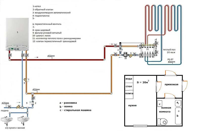
Before assembling a manifold assembly for a heated floor, weigh your options - sometimes it’s easier to buy a ready-made structure. If you are going to buy a collector, it is better that all its parts and elements are from the same manufacturer. When assembling the unit yourself, you must select the material from which the main components of the unit will be assembled: copper, steel, polymers or brass.
Also, when choosing an industrial design, it is important to consider the following parameters:
- How many heating circuits will there be in the system (usually from 2 to 12), the total length of the pipeline and the capacity of the circuits;
- Maximum permissible pressure in pipes;
- Possibility of expanding the heating system;
- Manual or automatic collector control;
- Electrical power of all components and assemblies;
- The diameter of the internal holes of the collector (throughput).

The most efficient operation of the assembled collector units can be ensured by connecting heating circuits of equal length to them. In order to equalize the length of the pipelines with sufficient accuracy, they are divided into equal sections, which are connected to the collector. The easiest way is to calculate the collector unit in a special computer program or on an online calculator, so that the phenomenon called “thermal zebra” does not appear, that is, uneven heating of the floor.
For the calculation you will need the following data:
- Type of decorative flooring;
- the area of the heated room and the plan for placing large objects in it;
- Material and diameter of circuit pipes;
- Boiler rated power;
- Type of floor insulation.
Important: when laying underfloor heating pipes, it is necessary to avoid pipe joints - this is prohibited by existing standards. It is also necessary to remember that the hydraulic resistance of the coolant increases with each turn of the pipeline and with increasing its length.

When designing a heated floor system, you first need to find the optimal location for installing the collector. Typically, the unit is installed in a manifold cabinet, and the cabinet itself is mounted at a height of 30-40 cm from the floor level next to the supply and return.
In order not to blame your own mistakes and ensure maximum heating of the heated floor pipes, study the instructions for connecting the collector. Then assemble the unit in the following sequence (this applies to an industrial manifold unit):
- Unpack the tubes for forward and reverse coolant supply. The tubes must have flow meters and supply valves. If the collector is multi-sectional, assemble the sections into one structure;
- From the assembled sections you need to assemble a unit on brackets (included in the kit);
- Next, we install shut-off valves, automation, sensors and other connecting fittings;
- We attach the unit to the wall or in a cabinet, install a thermostat, a servo drive and a circulation pump;
- We connect the pipes from the boiler and the pipes from the heating circuits of the “warm floor” system.

Now the connection diagram for the heated floor collector is pressed, after which the concrete screed can be poured. Thermal adjustments of the collector can be carried out after installation of the finishing coating.
DIY collector unit
A factory manifold is a fairly expensive product, so many craftsmen want to make it themselves. You will still have to buy many elements, but the cost will be cheaper. The easiest way is to solder a homemade manifold from PVC pipes and fittings Ø 25-32 mm. You will also need tees and bends of the same diameters, and shut-off valves.
Important: a homemade collector assembly has many joints, so all soldering must be carefully checked, and not only during assembly, but also during operation of heated floors.

The number of valves and fittings is calculated by the number of heating circuits. The tools you need are a soldering iron for propylene elements and attachments for it, special scissors for cutting pipes and a tape measure.
Marking the collector consists of marking and cutting pipes of the required length, observing the minimum distance between the tees. Valves and transitions are soldered to the PVC tees with a soldering iron. Fittings for connecting the pump are soldered to this structure. As you can see, everything is simple, but it is better to buy more complex collector units ready-made.
Today there are quite a large number of different autonomous heating systems. Each of them has its own advantages and disadvantages. One of the corners that ensures the efficiency and performance of a heating system is the manifold. Assembling such a structure for a heated floor with your own hands is quite simple if you know the layout of the collector and understand how it should work.
Manifold diagram for heated floors.
The collector is a node that includes the following elements:
- pipes that are made of plastic or metal;
- valves;
- pressure gauges;
- valves;
- fitting;
- other auxiliary units.
How does a collector work and what is it for?

An example of connecting a heated floor collector.
The design is used to mix the coolant that comes from various heating circuits. Subsequently, the device distributes the coolant along these circuits. By mixing, the temperature of the liquid will equalize. Therefore, the temperature in rooms that are heated will be stable.
You should know that the quality of the floor heating system will depend on the correct assembly of the collector structure.
The operating principle of the heating system is as follows: the hot coolant, after passing through existing circuits and pipes, will cool down, and under the action of the pumping structure or natural circulation will flow back into the collector. In this element, the coolant is mixed through a return pipe. The proportions of hot and cooled coolant can be adjusted by valves. Temperature control is carried out using special heat and pressure sensors. If the heating system is too long or there is no possibility of natural circulation in the house, then a circulation pump will need to be included in the collector structure.
A standard manifold consists of the following elements:

Diagram of a water heated floor.
- two-way or three-way mixing valve;
- shut-off valves;
- balancing valves;
- temperature sensor;
- pressure gauge;
- circulation pump;
- element for automatic air exhaust;
- fitting;
- tees;
- adapters;
- nipples.
You will also need some other elements for installation.
The design functions as follows: if the temperature exceeds a certain value, the thermal head will close the valve, and a small amount of hot coolant will be supplied. As the coolant cools, the valve will supply more liquid. The heat carrier is supplied from the return pipe with a continuous pressure, and from the supply pipe - if necessary. Consequently, the average temperature of the liquid will remain constant.
Advantages of a collector circuit for underfloor heating

Collector piping diagram.
A warm floor with a collector system has a fairly large number of advantages. The main ones are the following:
- Hygiene. Warm floors of this type can be easily cleaned and disinfected.
- Safety. Residents often forget about the high temperature of the equipment used for heating. When using such a design, burns and various injuries are excluded.
- Comfort. The collector device will create invisible coziness and an increased level of comfort.
- Economical. Energy savings, compared to using heating radiators, can reach 50%.
- Long service period. In the collector device, the only element that can wear out is the pipe. The service life of such an element is 50 years.
How to choose a manifold for a heated floor?

Collector stabilization scheme.
Such a design should be selected based on how much money can be spent on its construction. In addition, there is a parameter that must be observed. A similar parameter is the number of outputs on the collector. This number will depend on how many pipes need to be connected to the collector structure.
It is not possible to correctly calculate the number of loops correctly in all cases. They differ from each other in terms of room area. In some rooms it may be necessary to install two loops. An approximate calculation of the number of such elements can be made based on the fact that there are 6.5 m/p of pipes per 1 m². The resulting value must be multiplied by the area of the heated room. The final number should be compared with the existing lengths of pipes in the coil. It should be noted that in some cases it is best to make several loops so that there is not a lot of extra pipe left from the bay. You can take a collector with one more circuit, and plug the extra one.
Why do you need to install valves in the manifold?

Installation diagram of the collector and sensors.
A two-way valve will allow the coolant to flow in one direction, but it has a small capacity. The advantage of using a two-way valve is that in this case the coolant will flow smoothly and without fluctuations. Such devices have low throughput, and therefore are used in small rooms. The latest valve models can be equipped with a servo drive. Such an element is an engine with a valve placement sensor. Using a servo drive, you can open and close the fluid passage hole with precision.
A three-way valve will mix or separate coolant flows. In the body of the structure there are several pipes through which the element is connected to the heating pipes. The valve will receive fluid from the boiler, transfer it to the heating system, and also receive fluid from the return pipe in order to mix the latter with the hot supply. It is recommended to install a three-way valve in autonomous heating systems at the outlet of the collector system, where it is not necessary to limit the flow rate during uniform mixing.
With prolonged use, the valve may become clogged. To make it easy to replace such an element, a detachable coupling for connecting all elements should be used in the connection.
If the thermal fluid distribution scheme involves the installation of several collectors, then at the output of each element you will need to install a splitter with a structure for air exhaust.

Types of absorbers in vacuum tubular collectors.
Air is exhausted from the top of the splitter. The drain valve should be installed at the bottom of the structure. It will be used to drain the coolant during the repair of the heating system.
Some heating system designs do not require mixing of liquids; in such cases, valves may not be installed. To maintain a constant temperature in such systems, you will need to install a circulation pump. Such a design must be installed directly in the return pipe so that unnecessary intake of coolant from the heating system can be eliminated.

Types of collectors.
You can install a similar structure for a heated floor yourself. The distribution manifold is in most cases located in a manifold cabinet or a separate room, which is hidden in the wall. When installing the structure, you should consider the following nuances:
- You should try to place the distribution manifold at the highest point of the heating system in relation to the level of the placed loops. This is necessary so that, if necessary, air can be removed from the installed pipes.
- The distribution manifold should be located in the central part of the premises that are heated.
- You will need to connect circuits of the same length to one structure. If no such contours are available, the length should be as close as possible to the length of the element that is placed nearby.
Additional devices that are installed in manifolds

Diagram of the solar collector.
To automatically adjust the floor heating device, weather sensors can be installed in the collector structure. If it gets sharply cold outside, the heating intensity will increase. The weather sensor will send signals to turn the boiler on and off. It is worth noting that manual adjustment is ineffective. Sensors that depend on the weather will check the temperature several times per minute. If necessary, the servos will rotate the valve in either direction by 5°.
In order to assemble a simple collector, you need to prepare the following elements:
- mixing valve;
- nipple;
- adapter;
- tee;
- knee;
- coupling;
- circulation pump;
- ball valve;
- manifold connector;
- collector;
- external and internal connectors;
- device for air removal.

Vacuum manifold diagram.
It is also not very difficult to assemble a multi-circuit manifold for a heated floor with your own hands. It includes the following elements:
- thermal head with sensor;
- mixing valve;
- coupling;
- screw;
- tee;
- nipple;
- circulation pump with connected taps;
- stub;
- collector device;
- Ball Valves;
- fitting;
- union nuts;
- metal-plastic pipes.
If you plan to connect pipes of the “warm floor” system to the collector structure, then crimp fittings should be used to fix them. Before fixing to the pipe, you need to make a shallow chamfer so that the pipe can fit snugly into the seat for seating. After installing and connecting the collector structure to the boiler and to the heating system, you will need to pressurize the pipes and check their functionality. Pressure testing should be carried out for approximately 3-5 hours. In this case, even with a small heat, she will be able to express herself. The system will be warmed up at maximum level for several hours. The entire collector structure must be placed in a special cabinet, which is installed on the wall near the heating boiler or near the connection point to the heated floor.
Standard designs of this type are in most cases designed for 2-12 circuits. Today in construction supermarkets you can find devices of varying levels of complexity. The simplest device is in the form of a pipe, the standard hole diameter is 1 inch, and the diameter of the outlet channel is 0.5 inches. In this case, similar elements are equipped with shutters. For such a design, you need to purchase pumping equipment, an air release valve and a control system. It is not necessary to install servos and thermometers. In the process of purchasing or making a structure for a heated floor with your own hands, you should be guided by your own financial capabilities. You also need to consider what type of structure will be needed.
Almost anyone can assemble a collector structure. To do this, you should use one of the existing schemes.


