Homemade electronic musical instrument. Radio circuits, electrical circuit diagrams, circuit diagrams for beginners, sensory musical instruments
The ability of electronic devices to reproduce various sound effects is widely used in the design of modern electric musical instruments. Do-it-yourself musical instruments can be various attachments and imitators, giving an unusual “electronic” sound to traditional instruments - guitar, drum, piano.

Any audio frequency generator produces electrical vibrations, which, when fed to an audio amplifier, are converted by its dynamic head into sound. The tonality of the sound depends on the oscillation frequency of the generator.
If you use a set of resistors of different resistances in the generator and include them in the frequency-setting feedback circuit, you will get a simple electric musical instrument on which you can play simple melodies. The diagram of such a tool is shown in the figure below.

DIY musical instruments. Audio range generator circuit
The generator is made on transistors VT1 and VT2 of different structures according to a well-known circuit. Generation is formed due to positive feedback between the output and input circuits of the amplifier stages on the indicated transistors. The frequency of the generated oscillations can be changed by connecting either capacitor C1 or C2, as well as one of the resistors Rl - R8 (tool keys SB1 - SB8), into the feedback circuit with switch SA1. When the moving contact of the switch is in the position shown in the diagram, when you press the keys, the sounds of the first octave will be heard. If the moving contact of the switch is moved to the opposite position, you can receive sounds of the second octave. You only need to press one of the keys. If two keys are accidentally pressed, two parallel-connected resistors will be connected to the feedback circuit, and the frequency of the generator will not correspond to any of the sounds of a given octave. Moreover, the frequency of the generator will be higher than when pressing any of the two keys separately.
Resistor R9 limits the maximum frequency of the generator, and R10 limits the maximum undistorted sound volume.
Trimmer resistors - SPZ-16, constant resistors - MLT-0.25 capacitors - MBM. Transistor VT1 can be, in addition to that indicated in the diagram, MP38, MP38A or another low-power silicon transistor of n-p-n structure with a static current transfer coefficient of at least 50. Transistor VT2 should also be taken with the same coefficient - it can be of the G1213 - P217 series . Dynamic head - power 0.5 - 1 W, for example 1GD-18, 1GD-28. Power source - 3336 battery. Switch and switch - any design. The keys can be ready-made, say, from a children's musical instrument-toy, or home-made. In any case, contacts are installed under them, for example, from electromagnetic relays (preferably telephone ones), which will close when the keys are pressed. It is possible to use small-sized buttons, for example KM1-1. The main parts of the Tool can be mounted on a board (Fig. 82) using a hinged or printed method. The board is placed inside a case (Fig. 83) of any design. The dynamic head and controls (keyboard, switch, switch) are mounted on the front wall of the housing. The power source is mounted inside the housing or on the bottom (removable) cover.
Tuning a musical instrument is done with your own hands by installing sliders of adjusted resistors to obtain the appropriate tone. The resistances of the resistors must be such that fixed tones are obtained from “C” (or “A”) of the first octave to “C” (or “A”) of the second at intervals of one tone. Tuning is done using the sounds of a grand piano, piano, accordion or other musical instrument. First, by pressing the key - button SB8, by selecting the position of the resistor R8 slider, tune the generator to the frequency of the first initial tone - “C” or “A” of the first octave (this key should be on the left, on the musician’s side, end of the keyboard). Then press the SB7 key and select the position of the slider of resistor R7 to achieve the sound of the next tone - “D” (or “B”), etc. A slight shift in the musical scale of the instrument can be accomplished by appropriate selection of resistor R9.
The capabilities of a musical instrument with your own hands can be expanded by using a keyboard with 12 keys. Then, in addition to the main tones, additional tones will appear (“C sharp”, “A flat”, etc.) - The volume of the sound depends on the voltage of the power source. Increasing it to 9 V increases the volume, but at the same time, you may have to mount the powerful transistor VT2 on a small radiator in the form of a U-shaped corner bent from sheet aluminum 1...2 mm thick.
This is the first do-it-yourself musical instrument, which marked the beginning of a new direction in radio electronics - electronic music (electromusic for short). It was developed in 1921 by the young Petrograd physicist Lev Termen. An unusual electric musical instrument was named after the inventor. It is unusual in that it does not have a keyboard, strings or pipes with the help of which sounds of the desired tonality are obtained. Playing the theremin is reminiscent of the performance of a magician-illusionist - a wide variety of melodies sound from the dynamic head with barely noticeable manipulations with one or two hands near the metal rod-antenna sticking out on the body of the instrument.
The secret of the theremin is that it contains two independent oscillators that produce oscillations of a very high frequency - about a hundred thousand hertz. But the frequency of one of the generators can be changed by a kind of variable capacitor formed by the player’s hand and a metal antenna pin connected to the frequency-setting circuit of the generator. Approaching the hand to the antenna or removing it leads to a change in the total capacitance of the frequency-setting circuit, and therefore the frequency of the generator.
The signals from both generators are fed to the mixer. At the output of the mixer, a difference signal is released, which is amplified by an AF amplifier and reproduced by a dynamic head. In the initial state, the frequencies of both generators are the same, there is practically no difference signal, and no sound is heard. But as soon as you bring your hand closer to the antenna, a difference signal appears and a sound is heard in the head. Its tone is changed by hand moving closer to the antenna or moving away from it.

DIY musical instruments. Theremin diagram
This is the principle of operation of any theremin. The difference between the designs lies in the circuit design of individual components - generator, mixer, amplifier, as well as in the presence of components that allow obtaining original shades of sound or sound effects.
It is best to start getting acquainted with the theremin, of course, with a simple design, for example, shown in Fig. 84. A theremin was assembled on three integrated circuits. The first, tunable generator uses the DD1 chip. A multivibrator is made on elements DD1.1 and DD1.2, and a separating stage is made on DD1.3. The oscillation frequency of the multivibrator depends on the resistance of the resistor R1, the capacitance of the capacitor C2 and the capacitance between the antenna WAl and the common wire of the instrument, which is formed by the performer’s hand brought to the antenna. To obtain maximum sensitivity of the generator to the capacitance of the arm antenna, the frequency of the generator is chosen relatively high - hundreds of kilohertz.
In the second generator, with a fixed frequency, the DD2 microcircuit operates, the elements of which are used in the same way as the elements of the first generator microcircuit. The frequency of the generated oscillations can be changed within small limits using the variable resistor R2 “Frequency”.
From the output of each generator, the signal enters through a matching stage to its “own” input of the mixer, made on the DD3 microcircuit. If at one input there is a signal with frequency f1, and at the other f2, the output of the mixer will be signals with frequencies f1 ± f2. Moreover, the amplitude of the difference frequency oscillations will be tenths and even units of volts, which allows you to do without an additional AF amplifier and connect the dynamic head BA1 to the mixer output through capacitor C4, transformer T1 and variable resistor R4 “Volume”. Fluctuations of the total frequency are not reproduced by the dynamic head.
To increase the volume of the sound of a musical instrument with your own hands, all the logical elements of the DD3 chip are connected in parallel. The sound volume can be smoothly changed using variable resistor R4.
The theremin is powered by a GB1 source. To prevent mutual influence of generators, voltage is supplied to each of them through an RC filter. The current consumed by the tool is 7... 10 mA.
In addition to those indicated in the diagram, microcircuits K561LE5, K561LA9, K561LE10 (DD1 and DD2) can be used; K561LE5 K561LE6, K561LA7 - K561LA9, K561LE10 (DD3) or other similar microcircuits of the K176, K564 series. Capacitors C1 - SZ can be KD, KT, KM, the rest - K50-6, K53-1. Variable resistors - SPO, SP4-1, constant resistors - MLT-0.25 or other small ones, switch - MT1, power source - Krona battery or battery 7D-0.1. Transformer - output from any small-sized transistor receiver (one half of the primary winding is used). Dynamic head - power 0.1 - 0.25 W, for example 0.1GD-6, 0.2GD-1.
All parts, except the power supply, are mounted on a printed circuit board made of single-sided foil fiberglass laminate with a thickness of 1...1.5 mm. It is also the front panel of the instrument. Variable resistors and a switch are installed in the holes of the board, the transformer and dynamic head are glued. Opposite the head diffuser, holes are drilled in the board and covered from the mounting side with loose fabric. The leads of the parts are soldered to the board conductors.
The board is attached to a metal case with dimensions ZOX X75X145 mm. A power battery is placed inside the case and connected to the board with a multi-core insulated mounting wire. You can, of course, use the connector from a used Krona to connect the battery.
Contact XT1 is an M4 screw passed through a hole in the board and secured externally with a nut. The screw head must be securely connected to the contact pad of the board to which capacitor C1 is soldered.
Before playing the theremin, an antenna is attached to the screw - a piece of metal tube with a diameter of 6 and a length of 300...500 mm with a thread at the end.
If the installation is completed without errors and the parts are in good condition, the theremin begins to work immediately. They use it like this. Turning on the power, set resistor R2 to the so-called zero beat mode, when the frequencies of both generators are equal and there is no sound in the dynamic head. At the same time, when you bring your hand to the antenna, the sound should appear. By more accurately setting the resistor R2 slider, the sound appears at the greatest possible distance between the hand and the antenna. The pitch of the sound should increase as the hand is brought closer to the antenna.
To increase the sensitivity of the instrument, while playing, you need to touch the body or tuning knob with one hand (it must be metal, securely connected to the resistor body, and therefore to the common wire of the instrument), and select a melody with the other.
You can increase the volume of the theremin sound by connecting an audio amplifier, such as a radio or tape recorder, to the mixer output. For these purposes, it is advisable to install a connector on the body of the instrument.
The drum is one of the popular DIY musical instruments that beginner radio enthusiasts love to assemble, but it is very bulky. Reducing its dimensions and making it more convenient to transport is the desire of almost every ensemble. If you use the services of electronics and assemble an attachment to a powerful amplifier (and today it is an integral part of the ensemble’s equipment), you can get an imitation of the sound of a drum.
If you use a microphone, an amplifier and an oscilloscope to “view” the sound of a drum, you will be able to discover the following. The signal on the oscilloscope screen will flash in the form of a splash, reminiscent of a falling drop of water. True, it will fall from right to left. This means that the left side of the “drop” has a steep front, caused by hitting the drum, and then follows a damped decline - it is determined by the resonant properties of the drum. Inside, the “drop” is filled with almost sinusoidal vibrations with a frequency of 100...400 Hz - this depends on the size and design features of the instrument.
Such electrical oscillations can be generated, for example, by a shock excitation circuit if a triggering pulse is applied to it, or by a sound vibration generator that is in a inhibited (standby) mode at the moment of its short-term activation. Let's focus on the second option and get acquainted with the diagram of the attachment shown in Fig. 87.
An audio frequency generator is assembled on transistor VT2. Oscillations in it are excited due to the action of positive feedback (POF) between the collector and the base of the transistor. PIC is carried out by changing the phase of the collector signal by 180°, which is achieved using a three-link chain C1 - SZ, R4 - R6. The frequency of the generated signal depends on the ratings of these parts and can range from 100...400 Hz.

DIY musical instruments. Electronic drum circuit
The standby mode of the generator is obtained by shunting resistor R4 of the phase-shifting circuit with the resistance of the drain-source section of the field-effect transistor. And it, in turn, depends on the bias voltage at the transistor gate, set by variable resistor R2. The higher the bias voltage, i.e., the higher the variable resistor motor is located in the circuit, the lower the resistance of the indicated section, the stronger the shunting of resistor R4.
The initial bias voltage applied to the terminals of resistor R4 is formed by the divider R1VD1, in other words, the forward voltage of the diode is used. In this case, the diode, together with resistor R1, acts as a kind of parametric voltage stabilizer.
The resulting generator signal is fed through connector XS1 to an audio power amplifier.
To “hit” the electronic drum, you need to press the SB1 button. Through its closing contacts, capacitor C5 and diode VD2, a voltage pulse of positive polarity will be sent to the base circuit of the generator transistor. The generator will be excited and an audio frequency signal will pass through to the power amplifier. The duration of the signal, in other words, the duration of the drum sound depends on the position of the variable resistor R2 slider: the closer it is to the upper terminal in the circuit, the longer the sound. A second “kick” will sound after the button is released and pressed again.
The field-effect transistor can be of the KP302 series with letter indices A or B, a bipolar one - from the KT312 or KT315 series with indices B - G and a possibly high current transfer coefficient. Diode VD1 - any of the D226 series, VD2 - any of the D9, D18, D20 series. Fixed resistors - MLT-0.25, variable - SP-1. Capacitors C1 - SZ - MBM, C4 - K50-6, C5 - type KM or KLS. Power source - "Krona".
Some of these parts are mounted on a board, which is then installed in a small case, preferably metal. On the front wall of the case there is a variable resistor, a power switch and a connector, and on the top there is an SB1 button. The battery is located inside the case - it is connected to the parts of the set-top box with pieces of insulated mounting wire. Of course, for the convenience of replacing the battery, it can be connected through the connector from the used Krona, but this is not necessary, since the current consumed by the set-top box does not exceed 4 mA, and the battery energy will last for a long time.
Setting up the set-top box comes down to setting the constant voltage on the collector of transistor VT2 to about 5 V by selecting resistor R3. If it is necessary to change the tonality of the drum sound, you should install capacitors C1 - SZ of other values (but always the same). When checking and setting up the set-top box, its operation is controlled by high-impedance headphones TON-1, TON-2 or similar, connected to the connector through a capacitor with a capacity of 0.01...0.1 μF.
When performing various musical works, several drums are usually used, each of which has its own tonality. In the electronic version, for each drum you can make a separate attachment with different capacitors C1 - SZ and connect one or another simulator to the amplifier either by rearranging the plug from the power amplifier, or using a switch, for example a push-button one. In this case, you should remember to increase the length of the connecting wires and shield them to avoid the appearance of AC hum in the loudspeaker.
An option is possible in which all set-top boxes are mounted in a common housing, and their outputs are connected to the XS1 connector via a push-button, key or biscuits switch. To power such a design, you need to use a higher power source, for example, made up of 373 elements, or a mains rectifier with a constant output voltage of 8...10 V.
The popularity of the electric guitar today is largely due to the ability to connect electronic attachments to it, allowing you to obtain a wide variety of sound effects. Among electric guitarists you can hear words unfamiliar to the uninitiated: “wah”, “booster”, “distortion”, “tremolo” and others. All these are the names of the effects obtained while playing melodies on an electric guitar.
The story will be about some attachments for obtaining similar effects. All of them are designed to work both with industrial pickups installed on a regular guitar, and with homemade pickups made according to descriptions in popular amateur radio literature.

An excellent way to increase the volume of a guitar is a special musical instrument - a guitar pickup that converts sounds into an electrical signal, amplified by an electro-acoustic system and again converted into sound, but many times more powerful.
Schemes of the simplest electronic devices for beginner radio amateurs. Simple electronic toys and devices that can be useful for the home. The circuits are based on transistors and do not contain scarce components. Bird voice simulators, musical instruments, LED music and others.
Nightingale trill generator
The nightingale trill generator, made on an asymmetric multivibrator, is assembled according to the circuit shown in Fig. 1. The low-frequency oscillatory circuit formed by the telephone capsule and capacitor SZ is periodically excited by pulses generated by the multivibrator. As a result, sound signals are formed that resemble nightingale trills. Unlike the previous scheme, the sound of this simulator is not controlled and, therefore, more monotonous. The sound timbre can be selected by changing the capacitance of the capacitor SZ.
Rice. 1. Generator-simulator of nightingale trills, device diagram.
Electronic copycat of the canary singing

Rice. 2. Circuit diagram of an electronic canary singing imitator.
An electronic imitator of the canary's singing is described in the book by B.S. Ivanov (Fig. 2). It is also based on an asymmetric multivibrator. The main difference from the previous circuit is the RC circuit connected between the bases of the multivibrator transistors. However, this simple innovation allows you to radically change the nature of the generated sounds.
Duck quack simulator
The duck quack simulator (Fig. 3), proposed by E. Briginevich, like other simulator circuits, is implemented on an asymmetric multivibrator [R 6/88-36]. The telephone capsule BF1 is included in one arm of the multivibrator, and the LEDs HL1 and HL2 connected in series are included in the other.
Both loads work alternately: either a sound is made, or the LEDs flash - the eyes of the “duck”. The tone of the sound is selected by resistor R1. It is advisable to make the switch of the device based on a magnetically controlled contact, or a homemade one.
Then the toy will turn on when a disguised magnet is brought to it.

Rice. 3. Scheme of a duck quack simulator.
Rain noise generator
Rice. 4. Schematic diagram transistor "rain noise" generator.
The “rain noise” generator described in the monograph by V.V. Matskevich (Fig. 4), produces sound pulses that are alternately reproduced in each of the telephone capsules. These clicks vaguely resemble raindrops falling on a windowsill.
In order to make the droplet fall random, the circuit (Fig. 4) can be improved by introducing, for example, a field-effect transistor channel in series with one of the resistors. The gate of the field-effect transistor will be an antenna, and the transistor itself will be a controlled variable resistor, the resistance of which will depend on the electric field strength near the antenna.
Electronic drum attachment
Electronic drum - a circuit that generates a sound signal of the appropriate sound when touching a sensor contact (Fig. 5) [MK 4/82-7]. The operating frequency of generation is in the range of 50...400 Hz and is determined by the parameters of the RC elements of the device. Such generators can be used to create a simple electric musical instrument with touch control.

Rice. 5. Schematic diagram of an electronic drum.
Electronic violin with touch controls

Rice. 6. Circuit of an electronic violin using transistors.
A sensor-type electronic “violin” is represented by a circuit given in the book by B.S. Ivanov (Fig. 6). If you put your finger on the touch contacts of the “violin”, the pulse generator, made on transistors VT1 and VT2, is turned on. A sound will be heard in the telephone capsule, the height of which is determined by the electrical resistance of the area of the finger applied to the touch plates.
If you press your finger harder, its resistance will decrease, and the pitch of the sound will correspondingly increase. The resistance of the finger also depends on its humidity. By changing the degree of pressing of your finger to the contacts, you can play a simple melody. The initial frequency of the generator is set with potentiometer R2.
Electric musical instrument

Rice. 7. Diagram of a simple homemade electric musical instrument.
Electric musical instrument based on a multivibrator [V.V. Matskevich] produces rectangular electrical pulses, the frequency of which depends on the resistance value Ra - Rn (Fig. 7). Using such a generator, you can synthesize a sound scale within one or two octaves.
The sound of rectangular signals is very reminiscent of organ music. Based on this device, a music box or organ can be created. To do this, contacts of various lengths are applied around the circumference of a disk rotated by a handle or an electric motor.
Pre-selected resistors Ra - Rn are soldered to these contacts, which determine the pulse frequency. The length of the contact strip determines the duration of the sound of a particular note when the common movable contact slides.
Simple color music using LEDs
A color and musical accompaniment device with multi-colored LEDs, the so-called “flashing light,” will decorate the musical sound with an additional effect (Fig. 8).
The input audio signal is divided by simple frequency filters into three channels, conventionally called low-frequency (red LED); mid-frequency (green LED) and high-frequency (yellow LED).
The high-frequency component is isolated by the chain C1 and R2. The “mid-frequency” component of the signal is isolated by a sequential type LC filter (L1, C2). As a filter inductor, you can use an old universal head from a tape recorder, or the winding of a small-sized transformer or inductor.
In any case, when setting up the device, you will need to individually select the capacitance of capacitors C1 - S3. The low-frequency component of the sound signal passes freely through circuit R4, NW to the base of transistor VT3, which controls the glow of the “red” LED. “High” frequency currents are short-circuited by the capacitor SZ, because it has extremely little resistance to them.

Rice. 8. Simple color and music installation using transistors and LEDs.
LED electronic "guess the color" toy
The electronic machine is designed to guess the color of the LED that turns on (Fig. 9) [B.S. Ivanov]. The device contains a pulse generator - a multivibrator on transistors VT1 and VT2, connected to a trigger on transistors VT3, VT4. A trigger, or a device with two stable states, alternately switches after each of the pulses that arrive at its input.
Accordingly, the multi-colored LEDs included in each of the trigger arms as a load are illuminated in turn. Since the generation frequency is quite high, the blinking of the LEDs when the pulse generator is turned on (by pressing the SB1 button) merges into a continuous glow. If you release the SB1 button, generation stops. The trigger is set to one of two possible stable states.
Since the switching frequency of the trigger was quite high, it was impossible to predict in advance what state the trigger would be in. Although there are exceptions to every rule. Players are asked to determine (predict) which color will appear after the next launch of the generator.
Or you can guess what color will light up after releasing the button. With a large set of statistics, the probability of equilibrium, equally probable illumination of LEDs should approach the value of 50:50. For a small number of attempts, this relationship may not hold.

Rice. 9. Schematic diagram of an electronic toy using LEDs.
Electronic toy "who has the best reaction"
An electronic device that allows you to compare the reaction speed of two subjects [B.S. Ivanov], can be assembled according to the diagram shown in Fig. 10. The indicator that lights up first is the LED of the one who presses “their” button first.
The device is based on a trigger using transistors VT1 and VT2. To re-test the reaction speed, the power of the device should be briefly turned off with an additional button.

Rice. 10. Schematic diagram of the “who has the best reaction” toy.
Homemade photo gallery

Rice. 11. Schematic diagram of the photo gallery.
S. Gordeev's lighting system (Fig. 11) allows you not only to play, but also to train [R 6/83-36]. A photocell (photoresistor, photodiode - R3) is aimed at a luminous point or a sunbeam and the trigger (SA1) is pressed. Capacitor C1 is discharged through a photocell to the input of a pulse generator operating in standby mode. There is a sound in the telephone capsule.
If the pickup is inaccurate and the resistance of resistor R3 is high, then the discharge energy is not enough to start the generator. A lens is needed to focus light.
Literature: Shustov M.A. Practical circuit design (Book 1), 2003.
Electric musical instruments are popular among many beginning radio amateurs. For those who intend to start constructing such devices, repeating the diagrams below can be considered as the first step towards mastering the construction of more complex and modern instruments.
It is known that the spectra of sound vibrations used in electric musical instruments must satisfy certain conditions. In particular, so that the beginning and end of each note are not accompanied by pops, the envelope of sound vibrations must be smooth. The simplest single-voice instrument that satisfies these conditions can be assembled using just one transistor (Fig. 1). Each key of this instrument closes one of the contacts K1 - K12 and contact K13. In this case, the corresponding capacitor C1 - C12 forms an oscillatory circuit with the inductance of coil L1, which, together with transistor T1, forms a generator with autotransformer feedback.
The duration of the “attack” (appearance) of the sound after pressing a key is set by the time constant of the R1C13 chain. The duration of sound attenuation is determined by the capacitance value of capacitor C13. The table shows the capacitance values of loop capacitors for frequencies corresponding to the second octave of the musical scale.
|
Sound name |
G-sharp |
|||||||||||
|
frequency Hz |
||||||||||||
|
Capacitors Cl - C12, |
Inductor L1 and transformer Tp1 have a core made of ShL6X10 plates. Coil L1 contains 900+100 turns of PEV-1 0.12 wire. Winding I of the transformer contains 600, and winding II - 150 turns of the same wire. Resistors and capacitors - any type. As 77, you can use transistors like MP39 - MP42 of any letter series.
When building the tool, you should pay attention to the fact that contacts K1 - K12 close earlier and open later than contact K13. Resistor R3 is selected such a value that the occurrence of oscillations is reliably ensured, and the collector current does not exceed 4 mA.
In Fig. Figure 2 shows a variant of the instrument diagram that allows you to obtain damped sounds (plucked in nature). In the initial position, capacitor C13 is charged to the voltage of battery B1. When you press any key K1 - K12, contacts 2, 3 are closed and voltage is supplied to the generator from capacitor C13, the discharge time of which depends on the data in the circuit R4C14. This circuit determines the duration of the sound “attack”. The duration of its Attenuation depends on the total value of the capacitances of capacitors C13, C14 when the K1 - K12 keys are pressed and the capacitance of capacitor C14 when released. The capacitances of the loop capacitors Cl - C12 in this circuit are significantly smaller than in the circuit shown in Fig. 1, since at a lower frequency (the key is pressed) the circuit includes all the capacity needed to obtain a higher sound. All other data in the circuit, except for the nature of the contact groups, are the same as in the circuit of the previous musical instrument. The ratings of capacitors Cl - C12 can be easily calculated using the already known table.
Since circuits tuned to audio frequencies have a low quality factor, with a sharp change in the supply voltage, the frequency of the generator also changes noticeably. This is especially evident when the sound attenuates (the frequency increases). That is why the timbre of an instrument assembled according to the diagram in Fig. G, acquires a “toy” character. The timbre of the instrument (Fig. 2) has a vague resemblance to the timbre of the ukulele.
To avoid changing the frequency of the sound during attenuation, you need to add another transistor (Fig. 3). In this circuit, the generator, assembled on transistor 77, operates at a constant supply voltage, and a smooth sound envelope is created by changing the amplifier supply voltage. performed on transistor T2. The duration of the sound “attack” is determined by the time constant of circuit R6C14, and the duration of attenuation is determined by the capacitance value of capacitor C14. In this diagram, as in the diagram in Fig. 1, contacts K1 - K12 should close earlier and open later than contact K13. The tap from coil L1 is made from the middle of the winding. Both transistors operate in modes close to the key one.
The duration of the pulse in the load - the dynamic head Gr1 - and, therefore, the nature of the sound can be changed using switch B2. Transistors 77, T2 - low-power, low-frequency (MP39 - MGT42). The rest of the data is the same as for the first tool.
A small number of parts in the diagram shown in Fig. 1, allows you to design such an electric musical instrument in the form of a toy piano. A sketch of the keyboard design is shown in Fig. 4. To the keys 3 (white) approximately 13 mm wide, cut out of electrical cardboard or white plexiglass, a strip of phosphor bronze foil 6 with a thickness of 0.2 mm is glued to the bottom. Springs 7 are also made from strips of this foil. Rubber tape 5 with a thickness of 3 - 5 mm serves as insulation between the upper and lower strips. At the same time, it creates a force that returns the keys to their original position. The tape from the edges should be glued to the top cover 1. The contact between the two strips of foil corresponds to contacts K1 - K12. During installation, capacitors C1 - C12 should be connected to spring 7, and not to key-contact 6. Contact K13 is formed between spring 7 and string 8 made of nickel and constantan wire without insulation with a diameter of 1 mm.
With this design of the key, any of the contacts K1 - K12 closes earlier and opens later than contact K13. The top strips of getinax 4 keep the keys from moving horizontally. Springs 7 are glued to the bottom strip 4, and a groove should be made with a file for each spring. To improve the contact between spring 7 and string 8, as well as between spring 7 and strip 6, it is necessary to make extrusions with a diameter of 1 mm on the corresponding parts. On strip 6, glued to the key, the extrusion is done in a direction parallel to string 8, and on spring 7 - perpendicular. In an electric musical instrument assembled according to the diagram in Fig. 2, under each key a contact group should be installed for switching, and pushers should be attached to the keys.
When designing a design in the body of a pocket receiver, you can use the output transformer from the Sokol receiver as Tpl (core ШЗ X 6, winding I contains 2 X 450 turns of PEV-1 0.09 wire, winding II - 102 turns of PEV-1 0 wire ,23). Half of the primary winding is connected to the emitter circuit of transistor 77. The same transformer is used as inductor L1 (Fig. 1, 2), but its windings are connected in series, and a winding containing 102 turns is connected to the emitter circuit (points “a”, “b”).
In Fig. Figure 5 shows a diagram of a large single-voice electric musical instrument, the range of which extends from the sound “C” of the first octave to the sound “E” of the second octave. The electronic part of the instrument consists of a tone generator, a vibrato generator and a low-frequency amplifier.
The tone generator is an asymmetrical multivibrator mounted on transistors T3, T4 and generating a sawtooth voltage. In such a generator there are no transient processes when its frequency changes. The frequency of the tone generator is changed by closing the key contacts K1 - K17, which include resistors Rl - R17 of various resistances in the emitter circuit of the transistor T3. The resistance values of these resistors are selected empirically when setting up the instrument.
The chain of resistors Rl - R17 is called frequency-setting. When one of the contacts, for example K1, is closed, the closure of any other contacts K2 - KP located to the left (according to the circuit) of it will not lead to a change in the resistance in the emitter circuit of the TZ transistor. In this case, the oscillator frequency is determined only by the resistance of the resistor Rl and will correspond to the highest tone of the instrument. This scheme for constructing a frequency-setting circuit is called an upper or direct sound selection circuit.
General adjustment of the tone of all sounds is carried out by variable resistor R29. The tone generator is designed to operate at a voltage of 7.2 V. Excess voltage is suppressed by variable resistor R31. When new batteries are installed, the slider of this resistor is moved to the left (according to the diagram) position, and as the battery discharges, to the right.
The vibrato generator is used to produce a vibrating sound. It is assembled on transistors 77, T2 according to a similar circuit and generates oscillations with a frequency of 5 - 7 Hz.
The low frequency amplifier is assembled using standard scheme on transistor 75. Capacitor C8 is used to change the sound timbre. It is turned on by the VZ toggle switch.
With the help of sockets Gn1, Gn2 the tool can be. connected to the input of an external amplifier.
The design uses low-power low-frequency transistors MP39 - MP42. The output transformer from the Sokol receiver is taken as Tpl. The keyboard (Fig. 6) is made of electrical cardboard with a thickness of 1 - 1.5 mm and consists of the following parts: 1 - sub-keyboard protrusion; 2 - white key; 3 - black key; 4 - gasket (suede or cloth); 5 - contact springs; 6 - plywood plate; 9 3 - nail; 8 2 - lace; 7 1 - key pad (velvet or cloth).
The slits in the cardboard for the black keys are made with a sharpened knife along a metal ruler. Plates 6 with keys 2 and 3 and other parts are glued together with “88” or “BF-2” glue. The keys are painted white and black. To hold the keys at the same level, a cord is attached to each of them, the tension of which is adjusted by bending nail 9 driven into the common keyboard rail. The contact springs 5 must be adjusted so that the pressing force is the same for all keys.
One of the design options for this electric musical instrument, made by the author of the circuit, Yu. Ivankov, is shown in Fig. 7. This is a musical toy “Electronic Grand Piano”,
Setting up the tool comes down to precise selection of the resistances of resistors R1 - R17. In this case, the vibrato generator must be turned off by switch B1. First, resistor R1 is selected. To do this, instead, turn on a variable resistor of 5 - 10 kOhm, and between its motor and the K1 contacts there is a constant resistor of 1 kOhm. By changing the resistance of the modified resistor, the oscillation frequency of the tone generator corresponding to the sound “E” of the second octave is set by ear using a model musical instrument (piano, accordion). The coincidence of the frequencies of the generator and the musical instrument is determined by the absence of beats. Then, an ohmmeter is used to measure the resistance of a temporarily connected chain of resistors and instead of them, a constant resistor R1 of the same resistance is connected to the frequency-setting circuit. In the same way, select the resistance of resistor R2 (the “E-flat” key of the second octave), and then sequentially the resistance of resistors R3 - R17 (notes: “D”, “D-flat”, “C”, “B”, “B”) flat", "A", "A-flat", "G", "G-flat", "F", "E", "E-flat", "D", "D-flat", "C" ).
After setting the tone generator, they begin to adjust the vibrato generator, which consists of selecting capacitor C1 so that the frequency is 5 - 7 Hz. The vibration depth is selected using resistor R23. If the vibration amplitude needs to be increased, then the resistance of resistor R23 should be reduced, and vice versa. Considering that in this circuit the vibration amplitude increases with the pitch of the sound, the vibrato generator must be adjusted in amplitude by pressing the upper keys of the instrument (K1 - KZ). To stabilize the frequency of the tone generator, you can replace the variable resistor R31 with a constant one of 510 Ohms and turn on the D808 zener diode (at 7.2 V) or KS168 (6.8 V) between it (point “a”) and the plus of the power source.
The tools can be powered from a Krona battery (Fig. 1 - 3) or from two 3336L batteries connected in series (Fig. 5).
Moscow, DOSAAF USSR Publishing House, 1976 G-80688 dated 18/SH-1976. Ed. No. 2/763з Zak. 766
Lately I've started putting together designs that didn't really satisfy me. Multivibrators, stroboscopes and triggers have ceased to please my eyes. I decided to “revive” my subsequent designs and add sound to them. This idea inspired me to create my first sound design - a sensory musical instrument. Here is his photo:
Its circuit is surprisingly simple - only eight parts, not counting the battery. Here is their list:
Resistor................................................. ....1.5 kOhm;
Resistor................................................. ....1 kOhm;
Resistor................................................. ....470 Ohm;
Resistor................................................. ....10 kOhm, variable;
Transistor................................................. .KT315B;
Transistor................................................. .MP42B;
Capacitor........................................100 nF ;
Speaker......................................................... .....sound resistance. coils 8 Ohm;
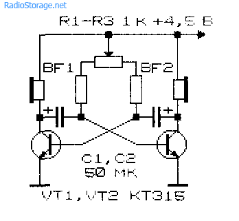
Now, let's move on to the diagram itself. It is shown in the figure:

This device works on this principle:
An asymmetrical multivibrator is assembled using transistors of different structures, the load of which is the dynamic head. In the state shown in the diagram, the multivibrator does not work. Naturally, there is no sound in the coil. But as soon as you connect a resistor between contacts E1 and E2, a sound will sound in the speaker, the tonality of which is determined by the resistance of this resistor. Power is supplied from a 4.5 V battery, but I took a “crown”.
The “tool” responds to resistance from 1 mOhm and below. You can play with one finger or two hands. In the first option, the sensors must be placed next to each other, and in the second, at a distance.
The device can be placed in a housing, or mounted as I did.
The KT315B transistor can be replaced with any of this series, and the MP42B can be replaced with a germanium transistor GT403B or a silicon transistor from the KT817 series.
List of radioelements
| Designation | Type | Denomination | Quantity | Note | Shop | My notepad |
|---|---|---|---|---|---|---|
| Bipolar transistor | KT315B | 1 | To notepad | |||
| Bipolar transistor | MP42B | 1 | To notepad | |||
| Capacitor | 100 nF | 1 | To notepad | |||
| Resistor | 10 kOhm | 1 | Variable | To notepad | ||
| Resistor | 1.5 kOhm | 1 | To notepad | |||
| Resistor | 470 Ohm | 1 |
For the first time, the diagram of this interesting electronic musical instrument - a toy - appeared in the magazine "Radio" in 1984, but later (in 2002) it was modified by I. Nechaev - a touch volume control was added. It is this modified scheme, despite its venerable age, that I want to offer to beginning radio amateurs. The design of the instrument is easy to repeat, quite visual and can become a good toy not only for a child, but also, as practice shows, for an adult. Let's take a look at the device diagram.
An audio frequency generator is assembled on elements DD1.1 and DD1.2, the frequency of which depends on elements R1, R2 and C1. The peculiarity of the generator is that its frequency can be changed by the light intensity - photoresistor R1 is responsible for this. The higher the illumination of the photoresistor, the lower its resistance and the higher the frequency of the generator. That is why the musical instrument is called “Svetofon”. Element DD1.3 is a buffer, and DD1.4, together with capacitor C2, is a touch volume control.
From the regulator, the signal goes to an amplifier assembled on transistor VT1 and is emitted by headphone BF1. So, the audio frequency signal from the output of element DD1.3 goes to a differentiating chain consisting of resistors R3 (it is connected to sensors E1, E2), R4 and capacitor C2. From it, short pulses are supplied to the input of element DD1.4, the amplifier and reproduced by the headphone. Moreover, if the sensors are not touched, then R3 does not participate in the operation of the circuit and the sound volume is minimal.
If you close the sensors with your finger, resistor R3 and skin resistance will turn on. This will allow the capacitor to charge in the pauses between pulses, and the more strongly, the more the sensors are blocked by the finger. Thanks to this, the pulse duration at the output of element DD1.4 will increase and the sound volume will increase. Thus, by covering the sensors with a finger, we will be able to regulate the sound volume within certain limits, and by changing the illumination of the photoresistor (for example, by rotating the device relative to the light source), we can adjust the tone frequency. After a little practice, it is quite possible to play a simple melody on such a musical instrument.
In place of DD1, K564LE5, K564LA7, K561LA7, VD1 - KD521A, KD103A, KD503A can work. Capacitor C3 is any electrolytic with an operating voltage of at least 10 V, the rest are any ceramic. Photoresistors FSK-K1, SF2-5, SF2-6 can be used as R1. Any telephone or dynamic head with a resistance of at least 50 Ohms will be suitable as a BF1 emitter.
If the head resistance is lower, then instead of the KT315 transistor you will have to install a more powerful one, for example, KT972 with any letter. The design of the traffic light is arbitrary; the sensors are made of a piece of foil-coated fiberglass laminate measuring 20 x 30 mm. To obtain two sensors along the strip, the foil is cut, the slot width is 0.5 ... 1 mm.