12 220V inverter circuits by hand. What will be the output
When it is necessary to create mains voltage in a car, special 12-220 converters are usually used. There are inexpensive standard inverters on sale for about 20-30 dollars. However, the maximum power of such devices is, at best, about 300 watts. In some cases, this power may not be enough.
You can get power for a powerful amplifier through small transformations. It is enough just to replace the secondary winding on a standard inverter. After this, you can get any value of the input voltage. For example, the power of a 400 Watt inverter will increase to 600 Watts.
To increase power at home, experts recommend using in a simple way. It will be necessary to replace the high-power bipolar switches with IRF 3205.
An inverter is used for operation, to which it is possible to connect 4 pairs of output transistors. Therefore, the device, after carrying out the necessary work, will be able to produce a power of about 1300 watts. If you buy a ready-made inverter with such parameters, its cost will increase to 100-130 dollars.
It is worth noting that the traditional push-pull circuit of the device does not contain protection against overheating, short circuit and output overloads.
The generator is based on a TL 494 microchip, which has an additional driver. It is necessary to replace low-power bipolar transistors with domestic analogues (KT 3107).
In order not to use powerful switches to supply power, the inverter is equipped with a remote control circuit.
In the driving part of the device, special SCHOTTTKI diodes type 4148 are used (domestic KD 522 is also suitable). The transistor in the remote control circuit is replaced with KT 3102.
After this, you can move on to the most important part of the project - the transformer. This element is wound on a pair of glued 3000 NM rings. Moreover, the size of each of them is 45x28x8. For a tighter fixation, the rings can be wrapped with tape.
Then the rings are wrapped on top with fiberglass (the cost in the store is no more than $1). It is quite acceptable to replace this material with fabric electrical tape.
Fiberglass is cut into small strips about 2 cm wide and no more than 50 cm long. The material for work has high heat resistance, and thanks to the thin base, the insulation looks neat.
For the primary winding you need 2x5 turns of wire, that is, 10 turns with a tap from the middle. The work is carried out with a wire with a diameter of 0.7-0.8 mm, and 12 wires are used for each arm. The process is presented more clearly in the following photographs.


The tourniquet is stretched, and 5 turns are evenly wound on both arms, stretching them across the entire ring. The windings must be the same.
The resulting elements have four outputs. The beginning of the first winding must be soldered to the end of the second. The solder location will be a tap for a power voltage of 12 V.
At the next stage of work, the ring must be insulated with fiberglass and covered with a secondary winding.

The secondary winding increases the output voltage. Therefore, when carrying out work you need to be as careful as possible and follow all safety precautions. It's worth remembering that high voltage dangerous. Installation of the device is carried out only with the power turned off.
The winding of the rings is carried out using a pair of parallel strands of 0.7-0.8 mm wire. The number of turns is about 80 pieces. The wire is distributed evenly throughout the ring. At the final stage, the product is additionally insulated with fiberglass.
When the inverter assembly is completed, you can begin testing it. The device is connected to a battery; for starters, a battery with a voltage of 12 V from an uninterruptible power supply will do. In this case, the “plus” of the power supply will go to the circuit through halogen lamp power 100 watts. It is worth paying attention that this lamp should not be lit before or during work.
After this, you can proceed to checking the field keys for heat generation. With a correctly assembled circuit, it should be practically zero. If there is no input load, and the transistors overheat, then you need to look for a non-working component in the device.
If the testing is successful, you can install the transistors on one common heat sink. For this purpose, special insulating gaskets are used.
Fundamental electrical diagram in *.lay format is in an archive file and will become available after downloading.
Comments (41):
#1 Snow White February 19 2015
Perfetto. Excellent This circuit seems to be what I was looking for about the transistor, very interesting. If you increase the number of turns, say three times, the current on KT 817 will also drop to 0.6. It doesn't work fast enough, is this the reason for the high current?
To be honest, I haven’t tried to increase the turns. As for the performance speed, yes, that’s why it was replaced with KT940. the current can be reduced further. From the lamp, take only the lamp itself and throw the board out of it. then the current is in the range of 0.3-0.35A..
#3 Selyuk May 12 2015
Everything is very “simple”, but where can I get the transformer cups??
#4 root May 12 2015
In the transformer design of this high-voltage converter there is no gap between the ferrite cups, so you can try using a ferrite ring or frame from a pulse transformer with a ferrite core (you can take it from a non-working computer power supply).
You will need to experiment with the number of turns and output voltage.
#5 pavel June 01 2015
What is the principle for calculating a transformer and selecting transistors for this inverter? I would like to make one with a power supply of 60 volts.
The cups were taken because they were just there, and the number of turns in such a core is needed less. I haven’t tried ferrite rings; it works fine on regular W-shaped ferrite. I don’t remember how many turns I wound, the primary one seemed to be 12 turns with 0.5mm wire, and the booster one was done by eye until the frame on the core was filled. The transformer was taken from a 4 by 5 cm monitor.
#7 Egor October 05 2015
I have a question for you: how many ohms is the resistor on the left at 220???
I'm just not very good at electronics)))
#8 root October 05 2015
If there are only numbers next to the resistor, that means the resistance is in Ohms. In the diagram, the resistor has a resistance of 220 ohms.
Tell me, is it possible to use your circuit to power the MTX-90 thyratron and not from 12, but from a 3.7 volt battery?
If possible, what are the best transistors to use? The MTX-90 has a small operating current - from 2 to 7 mA, and the voltage for ignition needs about 170 volts, well, you can experiment with this with a transformer (about voltage).
I don’t even know what to answer. Somehow I didn’t think about it.. Why do you need to power the thyratron from this circuit? In principle, it will work, of course, the only question is how... from 3.7 volts it is also possible, but the windings must be recalculated or selected experimentally.
#11 Oleg December 13 2015
People, tell us how to make an inverter from transistors from a Chinese typewriter on a control panel. Is it possible to install a ring ferrite core and is it possible to make a 3-fold difference in turns? I should make an inverter this way just for fun and to make it easier. And is it possible to set the input voltage to somewhere around 3V?
Answer please! I will be glad if you answer all my questions! I'm waiting for your answers!
#12 Alexander December 17 2015
I have 30/10 ferrite cups, is it possible to wind a trans on them and what number of turns should be wound, at least approximately.
#13 Alexander January 24 2016
Everything works great there, both the 15 watt lamp and the 20 watt one. More powerful transistors are simply needed. KT940 can be left alone, but 814 could at least be replaced with KT837. And if the current is high, you don’t need to rewind anything, you just need to increase the value of the resistor to 3.1k. And the transformer is not necessarily of this size, even a pulse generator will work from charging, transistors will still play a special role. p.s. These transistors have a power of no more than 10 watts
#14 Eduard February 01 2016
What kind of transistor can I replace KT814 with? Can I use 13005 or KT805?
#15 Alexander February 03 2016
Change it to KT805 - you'll scrape off a lot of power, because according to the datasheet, KT805 can give up to 60 watts
KT814 is p-n-p conductivity, and KT805 and 13005 n-p-n..., of course you can’t Eduard...
#17 Mars May 11 2016
Instead of KT814 I installed KT816.15W lamp pulled.
#18 sasha November 06 2016
I installed KT805 and KT837. primary 16v.0.5mm. secondary 230v. 0.3mm. lamp 23W. glows great.
#19 Eduard November 19 2016
March. counter question, what then can replace the KT940, so that the KT814 can be replaced with KT805 or 13005 and change the power polarity? An idea arose: I removed the 12-volt pulse transformer from the electronic transformer for halogen lamps, there is just a secondary of 12-14 turns and The primary is about 150-200 turns. If you deploy it as a booster and plug it into this circuit? I think it should work, but if you replace the combination of KT814 and KT940 with something more modern, then you can squeeze out up to 40 W of power? I also want to try it on the UC3845 PWM controller , the circuit there is generally primitive: a UC3845 microcircuit, in its circuit a frequency-setting resistor and a film capacitor, an IRFZ44 field-effect transistor and a transformer from an electronic transformer included in the circuit as a step-up, as a result we have up to 100 W of power at 12 volts
and why "..940 outputs in the old colors in abundance.. everyone has nowhere to put it... replace it with any reverse transistor, but you want 805, then yes..940 on forward conduction.... and change the polarity... but again -why do we all have so many of these transits in our bins...
#21 pavel February 09 2017
why do you need to increase the power of the circuit :)? What, will you use KrAZ batteries (190 a/h)?? this circuit makes sense, as a friend correctly said, if you use a bulb from a lamp with a burnt-out circuit. Otherwise, to hell with the button accordion: an LED lamp from the same battery, with the same light output, will illuminate many times longer!..
#22 pavel February 09 2017
Now about the transistors: you can change them, but you need to remember that any power transistor provides its declared power only when using an appropriate heat sink. this fact directly affects the dimensions of the entire device. and where will you get energy saving? l ampu more powerful than 30 watts = 150? I haven't seen it on sale. and I already talked about the battery for such a “pacifier” :). so, know your limits, inventors, good luck!
#23 Eduard February 24 2017
March, I just have a problem with the Soviet KT940 and KT814. Basically in my reserves I have imported powerful high-frequency bipolar transistors 13005 for 5 amperes 400 volts, and the like. They managed to light the flask at full brightness from a 30 W energy-saving device, while the transistor was slightly warm. And the Soviet KT814 and KT805 ARE GLUGGY BY THEMSELVES BOIL QUICKLY EVEN WITH A RADIATOR
I would not say that the KT805 is buggy... depending on which one you use. in plastic they are unreliable, there is such a thing, and then for some 80 years. take the 805 in metal, it’s generally an indestructible transistor. However, it is necessary to emphasize the fact that they are buggy not because they are bad, but because they were not entirely in capable hands, just
But you can even install imported microwave transistors, it will work!!! verified!!. In this article, I wasn’t trying to create a miniature lamp, but rather how to fix a burnt-out lamp at minimal cost. to serve again
the 814 collector should be grounded through a 10 µF capacitor, otherwise when switching the surge is very large.
The 814 transistor is in a half-open state - however, it needs a radiator.
It was easier to use a blocking generator.
what other 10 microfarad capacitor, what nonsense, is it really not clear from the photo that the miniature radiator will all fit into a pack of cigarettes. and using a blocking generator is no easier. there you need at least three windings. and the transistor will heat up there no less!!!
#28 IamJiva August 14 2017
blocking generator serves the same purpose, to provide feedback (bring the microphone to the speaker so that it buzzes), if you did without a microphone, why don’t you need it, here you got by adding a transistor, in blocking you can get by with one transistor, and turn the phase around with turns of the winding, which (allow ) can be independently connected in any polarity. You can squeeze out a lot of watts, but it’s difficult, part of the energy (for powerful lamps is significant, up to 90%) is lost on the diode bridge and electrolyte (in the lamp rectifier) that are cheap (especially if powerful) and 50Hz are suitable, at 50kHz smoke can already come from them and the voltage never appears to start the lamp, 50Hz diodes (simple, that is, not ultrafast or Schottky) do not have time to lock, and drain the charge back into the winding or somewhere else, this causes heating of everything and incorrect operation of the generator, the electrolyte has inductance (series) , and a short pulse it only “recognizes” but is in no hurry to carry out the order, while waiting for the command to set it aside... the current begins to increase to infinity or as long as they give, for 50Hz instantly, for 50kHz - never... the transistor needs to be fast, it can get warm and NO way, IRF840 2pcs, correctly used, provided on 4 4ohm columns of 500wt each, 2000Wt of power in class D, powered by +-85V (170V) TL494 PWM, Ir2112 driver in the gates, 4pcs ultrafast diodes shunt the SI and IC, varistors 400V BC 30V SI
2kW drum and bass power, they were a little warm on the same radiators as here, at the output there is a choke from the fuel assembly and 200 turns, at 2500wt they burned out without warning
It would be a good idea to bypass the output transformer of the primary with a diode, or better yet with a varistor (from flyback impulses possible in the event of a load disconnection, the selection of transistors and turns of the primary for maximum efficiency is as important and valuable as the ratio of sugar and vinegar with water + time on the timer in the microwave, so go away and take out the lollipops, the circuit works like a juggler you’ve never seen, they hope for the ease of transferring the ideal-harmony-efficiency-power to another circus and there’s no need for a jacket
One question for the author. This converter will pull an electric razor from Kharkov, Agidel, Berdsk, etc.
I need just such a miniature one that I can always build it into my shaving machine.
Just don’t write that there are plenty of battery-powered and wind-up electric shavers on sale. My dear to me.
She's been with me half my life.
Good luck.
#30 root January 21 2018
To power a 220V electric razor from the car’s on-board network, it is better to assemble some more reliable and powerful voltage converter. Here are a few similar schemes:
- Voltage inverter 12V to 220V from available parts (555, K561IE8, MJ3001)
- Simple voltage inverter 13V-220V for car (CD4093, IRF530)
Thanks for the links, but it’s too expensive and difficult to assemble on your knees.
I don't have such details. But the old color.tel. and there is a tape recorder. It's all there
People write that you can increase the power by replacing transistors with 805.837.
An electric razor consumes 30 watts. Maybe it will. What do you think.
I came across the Variom A ROM.
The trouble is that the P216G transistors can no longer be found, and one of them is not working. According to the parameters, the GT701A seems to be suitable, but here’s how to determine the resistors. There are only 4 of them, two pairs. I don’t think it will work just replacing both P216Gs with GT701A. Tell.
#33 root February 05 2018
Agu1954, P216 transistors can be replaced with GT701A or P210V. Below are the main operating limits of these transistors:
- P216G: Ukb, max=50V; Ik max=7.5A; Pk max=24W; h21e>5; f gr.>0.2 MHz;
- P210V: Ukb, max=45V; Ik max=12A; Pk max=45W; h21e>10; f gr.>0.1 MHz;
- GT701A: Ukb, max=55V; Ik max=12A; Pk max=50W; h21e>10; f gp.=0.05 MHz;
Replace two transistors P216 with GT701A (P210V). For safety reasons, the first connection of the circuit to the battery should be made through a 3A fuse.
P.S. Please ask questions not related to the diagram given in the publication on the forum or in our social groups VK and FB.
#34 Sergey February 16 2018
#35 root February 16, 2018
Hello, Sergey. An old, and no longer working, postal address was indicated. Fixed it with a new one.
#36 Sergey February 16 2018
This converter operates at a frequency far greater than 50Hz. somewhere in the region of 20-50 kHz. Even if you increase the power by replacing transistors with more powerful ones, the razor will still not work. the engine simply cannot physically operate at a frequency of tens of kilohertz
#38 Petro Kopitonenko November 19 2018
To lower the frequency of the current on the converter, you must try to increase the number of turns of the transformer, both the primary and secondary windings. Where am I coming from? 50 hertz transformers have big number turns. And high-frequency ones have a small number of turns. This is the same as in oscillatory circuits, the frequency depends on the number of turns. I soldered an experimental converter with a factory transformer at 50 hertz. There, two primary windings are wound with 40 turns instead of 10 turns according to the circuit. I could hear the transformer humming at a frequency of about 40 hertz by ear. If it were a frequency of 50 kilohertz, I would not hear anything!!!
#39 David June 13 2019
Or you can use a ready-made transformer in this circuit. For example, step-up transformer TP 30-2, just connect in reverse (to the 15 volt output winding)
#40 root June 15 2019
The circuit requires a high-frequency transformer; TP 30-2 or another network transformer with Sh-like or toroidal iron will not work here.
#41 Dmitry October 06 2019
Good day! The primary of the transformer must be equipped with a snubber. With the second transistor you are practically switching the inductance. And don’t care that the voltage is low! With a snubber chain it will be easier for transistors. Someone above already suggested shunting the 814 collector with a capacitance, but it went unheard. But better, of course, is a classic snubber - diode, resistor, capacitor.
You can literally use scrap materials. You can even take units from a simple uninterruptible power supply as a basis - it is, in fact, a double converter - first the voltage is reduced to 12 V to ensure the battery is charged.
And then the voltage is increased to 220 V, the current is converted from direct to alternating. Such devices can be used to power household equipment outside the home - drills, grinders, televisions, etc. It is not difficult to make such a device yourself, and its cost will be less than that of similar devices that are sold in stores.
Operating principle of the inverter
The second name of the converter is inverter. Essentially, it is pulse-width modulation. Power is supplied from a constant voltage source of 12 volts (in this case, from a battery). Pulses appear at the output of the device, the duty cycle of which changes. Depends on the ratio of time during which voltage is present or absent. When the duty cycle is equal to unity, the output has a maximum current value. As the duty cycle decreases, the current decreases.
The output voltage at any time is 220 V. Even the simplest 12V to 220V converter can operate in a wide frequency range - 50 kHz...5 MHz. It all depends on the specific scheme and the elements used in it. The voltage frequency is very high; it will be destructive for powering household equipment. To reduce it to the standard 50 Hz, it is necessary to use specially designed transformers. A PWM modulator allows you to create an alternating voltage from a direct voltage at the required frequency.
Feedback system
When there is no load on the PWM modulator, the duty cycle of the pulses is at a minimum level, the voltage value is 220 V. As soon as a load is connected to the device, the current will increase sharply and the voltage will drop, it will be less than 220 V. If you decide to make a voltage converter from 12 to 220 volts with your own hands, then be sure to take into account the presence of feedback. It allows you to compare the output voltage with a reference value.

If there is a difference in voltages, then a signal is sent to the generator, which allows you to increase the duty cycle of the pulses. Using this system, it is possible to achieve maximum output power and a more stable voltage. As soon as the load is turned off, the voltage jumps again above 220 V - the feedback system records this and reduces the duty cycle value of the pulses. And so on until the voltage levels out.
Working with a dead battery
When the duty cycle and output current change, the load on the power supply increases. This leads to its discharge and a decrease in voltage. And if a feedback system is used, it increases the duty cycle of the signals as much as possible, sometimes to the maximum - unity. Self-made 12/220 volt voltage converters without feedback react very strongly to dead batteries. During operation, the value of the output voltage necessarily decreases.

If you plan to connect equipment such as grinders, electric lamps, boilers or kettles, then reducing the voltage will not affect their operation. But if a converter is needed to connect television equipment, laptops, computers, servers, amplifiers, feedback is simply necessary. It allows you to compensate for all voltage surges, which will ensure stable operation of the devices.
Scheme selection
To make a 12/220 V voltage converter with your own hands, you need to select a specific circuit. Moreover, be sure to take into account the power of the devices that you plan to connect to it. Estimate approximately what load will be powered by the inverter. Be sure to add another 25% to the received power in reserve, there will be no excess. Based on the data obtained, you can choose a specific scheme. And, of course, one of the important points is

Assess your financial capabilities if you plan to purchase all the components. And you will need a lot of expensive elements. Fortunately, almost all of them are found in modern technology - in uninterruptible power supplies, power supplies for computers and laptops. By the way, a standard UPS can be used as a voltage converter; no modifications are even needed. Connect a more powerful battery to it and that’s it. But you will have to charge the battery from an additional power source - the standard one will not be able to produce the required current value.
Converter circuit elements

The standard design of an inverter for converting 12 V DC to 220 V AC consists of the following elements that can be found in any modern technology:
- PWM modulator is a specially designed microcontroller.
- Ferrite rings for the manufacture of HF transformers.
- Power field-effect transistors IGBT.
- Electrolytic capacitors.
- Constant resistances of various powers.
- Chokes for current filtering.
If you are not confident in your own abilities, you can independently assemble a converter using a multivibrator circuit. The transformer for such a device is suitable from a UPS or power supply for transistor TVs. This device has one drawback - its impressive dimensions. But setting it up turns out to be much easier than complex structures that work with high-frequency current.
Operation of inverters
If you decide to make a 12/220 voltage converter with your own hands using a simple circuit, then its power may be low. But it is quite enough to power household equipment. But if the power is above 120 W, then the current consumption increases to at least 10 amperes. Therefore, when used in a car, it cannot be plugged into the cigarette lighter socket - all the wires will melt and the fuses will fail.

Therefore, car inverters with a power exceeding 120 W must be connected to the battery using an additional fuse and relay. Be sure to lay the wire from the battery to the installation location of the car inverter. To turn on the converter you can use rocker switch or a button paired with an electromagnetic relay - it allows you to remove high current from the controls.
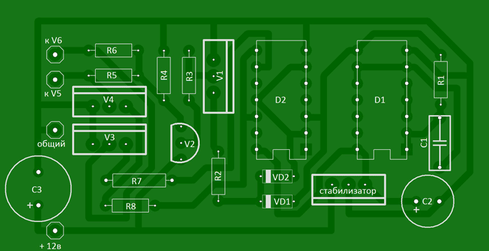
I propose a 12/220V voltage converter (inverter) circuit (power up to 500 Watt), powered by a 12V battery, which can be useful in a car and at home for lighting, for powering a TV, a small refrigerator, etc. The circuit is assembled on two 155 series microcircuits and six transistors. The output stage uses field-effect transistors that have a very low on-state resistance, which increases the efficiency of the converter and eliminates the need to install them on radiators that are too large.

Let's figure out how the circuit works: (see diagram and diagram). The D1 chip contains a rectangular pulse generator, the repetition rate of which is about 200 Hz - diagram “A”. From pin 8 of the microcircuit, pulses are sent further to frequency dividers assembled on elements D2.1 - D2.2 of microcircuit D2. As a result, at pin 6 of the D2 chip, the pulse repetition rate becomes half as much - 100 Hz - diagram "B", and at pin 8 the pulses become equal to the frequency of 50 Hz - diagram "C". Non-invertible 50 Hz pulses are removed from pin 9 - diagram “D”. An “OR” logic circuit is assembled on diodes VD1-VD2. As a result, the pulses taken from the pins of microcircuits D1 pin 8, D2 pin 6 form a pulse corresponding to diagram “E” at the cathodes of the diodes. The cascade on transistors V1 and V2 serves to increase the amplitude of the pulses necessary to fully open the field-effect transistors. Transistors V3 and V4 connected to outputs 8 and 9 of microcircuit D2 open alternately, thereby locking either one field-effect transistor V5 or another V6. As a result, control pulses are formed in such a way that there is a pause between them, which eliminates the possibility of through current flowing through the output transistors and significantly increases efficiency. Diagrams "F" and "G" show the generated control pulses for transistors V5 and V6.
A correctly assembled converter begins to work immediately after power is applied. When setting up, you should connect a frequency meter to the output of the device and set the frequency to 50-60 Hz by selecting resistor R1, and, if necessary, capacitor C1.
About details
Transistors KT315 with any letter index, KT209 can be replaced with KT361 with any letter index. We will replace the KA7805 voltage stabilizer with the domestic KR142EN5A. Any resistors with a power of 0.125...0.25 W. Almost any low-frequency diodes, for example KD105, IN4002. Capacitor C1 type K73-11, K10-17V with low capacity loss when warming up. The transformer was taken from an old tube black and white TV, for example: “Spring”, “Record”. The 220 volt winding remains, and the remaining windings are removed. Two windings are wound on top of this winding with PEL wire - 2.1 mm. For better symmetry, they should be wound simultaneously into two wires. When connecting the windings, take into account the phasing. Field-effect transistors are fixed through mica spacers on common radiator made of aluminum with a surface area of at least 600 sq.cm.

List of radioelements
| Designation | Type | Denomination | Quantity | Note | Shop | My notepad |
|---|---|---|---|---|---|---|
| Linear regulator | UA7805 | 1 | KR142EN5A | To notepad | ||
| D1 | Valve | K155LA3 | 1 | To notepad | ||
| D2 | D-trigger | K155TM2 | 1 | To notepad | ||
| V1, V3, V4 | Bipolar transistor | KT315B | 3 | To notepad | ||
| V2 | Bipolar transistor | KT209A | 1 | KT361 | To notepad | |
| V5, V6 | MOSFET transistor | IRLR2905 | 2 | Through mica spacers | To notepad | |
| VD1, VD2 | Diode | KD522A | 2 | KD105, 1N4002, etc. | To notepad | |
| C1 | Capacitor | 2.2 µF | 1 | K73-11, K10-17V | To notepad | |
| C2 | 470 µF | 1 | To notepad | |||
| C3 | Electrolytic capacitor | 2200 µF | 1 | To notepad | ||
| R1 | Resistor | 680 Ohm | 1 | To notepad | ||
| R2 | Resistor | 7.5 kOhm | 1 | To notepad | ||
| R3, R5-R8 | Resistor |
Often in life there is a need to obtain a voltage of 220V from a lower voltage, say, 12 Volts. For example, you need to connect Charger from a laptop to a car battery, this is no problem. In addition, inverters have found wide application in alternative energy. They are usually installed on wind turbines, hydroelectric power stations, etc., which in most cases generate low voltage.
Today we will look at how to make an inverter with your own hands. There are no complex electronics here, the set of components is very small, and the circuit is understandable to any beginner. All you need is to connect several resistors, transistors and a transformer. Intrigued? Then let's move on to studying the instructions!
Materials and tools used
List of materials:
- transformer 12-0-12V at 5A;
- 12V battery;
- two aluminum radiators;
- two TIP3055 transistors;
- two 100 Ohm/10 Watt resistors;
- two 15 Ohm/10 Watt resistors;
- wires;
- plywood, laminate (or other material for making the body);
- socket;
- thermal paste;
- plastic ties;
- screws and nuts, etc.


List of tools:
- soldering iron;
-
- ;
- wire cutters;
- screwdriver.
Inverter manufacturing process:
Step one. Check out the diagram
Check out the connection diagram for all elements. There is both a detailed electronic diagram and a simple, intuitive diagram of where and what wires to connect.


Step two. We assemble two circuits from resistors and transistors
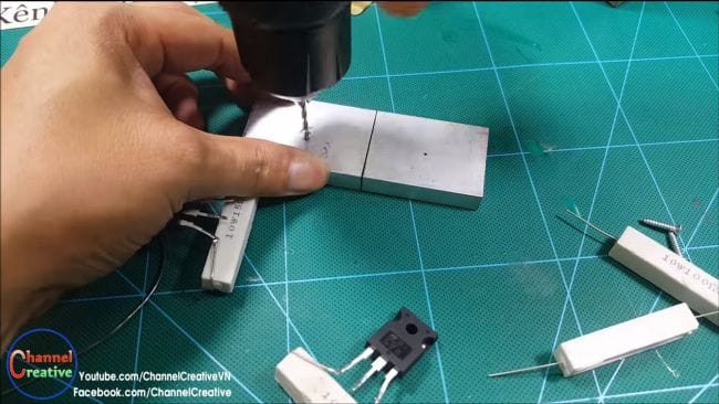
We take the transistor and attach it to a 15 Ohm resistor, as seen in the photo. We attach the second transistor in the same way.


Step three. Radiator
During operation, transistors will heat up, and if this heat is not removed, they may fail. Here you will need two radiators. We drill holes, apply thermal paste and firmly tighten the transistors to the radiators with self-tapping screws.


Step four. We connect two circuits using 100 Ohm resistors
We take two 100 Ohm resistors and connect the two circuits diagonally. That is, you need to solder the contacts to the two leftmost legs of the transistors, if you look at their front part.


Step five. Connecting the central legs
We take a two-wire cable and solder one wire at a time to the central contacts of the transistors. These wires are then soldered to the leftmost and rightmost pins on the transformer, as can be seen in the photo.


Step six. Jumper
According to the diagram, you need to install a jumper between the outermost and rightmost contacts of the transistors. We cut off a piece of wire and solder them to the paws.


Step seven. Further connection
We take another piece of wire, the author has it pink. Solder it to the central contact of the transformer, through it the positive from the battery will be supplied to the transformer.
You will also need a piece of white wire, this will be the negative from the battery, it needs to be soldered to the yellow wire, that is, the jumper installed earlier.


Step eight. Let's test!
Before you know it, the electronic part of the inverter has been assembled and you can test it! We connect the battery and measure the voltage with a multimeter. It jumps in the range of 200-500V.
First, the author decided to connect a very weak 5-watt light bulb to the inverter; it lit up without any problems.


Then a more serious 40-watt light bulb was connected, and it lights up as if it were plugged into an outlet at home, but in fact it is powered by a small 12V battery.


Finally, the author decided to connect a 15W fluorescent lamp, it also lit up without any problems.


We also decided to try connecting a mobile phone charger. The phone charges without any complaints.

Step nine. Assembling the body
To make everything safe and look aesthetically pleasing, we will make a housing for the inverter! To do this, you will need a socket, a piece of cable, and plywood, laminate or something similar. We cut the material into the required pieces to make a box. We screw the transformer to the base; for reliability, the author decided to fasten it with screws and nuts. As for the electronic part with transistors, it was decided to secure it with plastic ties. We drill holes and attach the lower 100 ohm resistors to the base.


The body can be assembled; for this purpose the author used hot glue. As for the top cover, you need to cut out a seat for the socket in it. The author's material is soft; he cuts out the window using a stationery knife. If the window is the right size, the socket should lock securely. On the reverse side it can be further strengthened with hot glue or epoxy.
It's time to install the cover; we attach it with self-tapping screws in order to have access to the insides of the inverter.